
Установка сигнализации Land Rover Discovery 3
Вся информация на английском языке, другой пока нет, если есть чем дополнить пишите в Обратная связь
Точки подключения для Пандоры
питание + замок зажигания коричневый
питание - там рядом болт на корпус родной.
подключение к КАН диагностическая колодка , 3 и 11 штырь в колодке, желто белый и желто синий.
2 аналоговых управляющих сигнала на центральную консоль для управления ЦЗ открытие, закрытие.
по левой стойке: RF + подключение к вебасто доп каналом + диагностическая лампочка.
модуль автоподзавода подключается на замке зажигания:
12+ постоянка - коричневый
стартер - бело/красный
АСС - белый
зажигание - желтый
Модуль обхода иммобилайзера плюсом на "желтый " в замке зажигания, управление минусом.
датчик температуры салона рядом с родным под рулем справа.
датчик температуры двигателя через резинку слева под рулем ушел в подкапотное.
Инструкция по установке сигнализации Дефа, точки подключения
Для просмотра фотографии откройте в отдельном окне
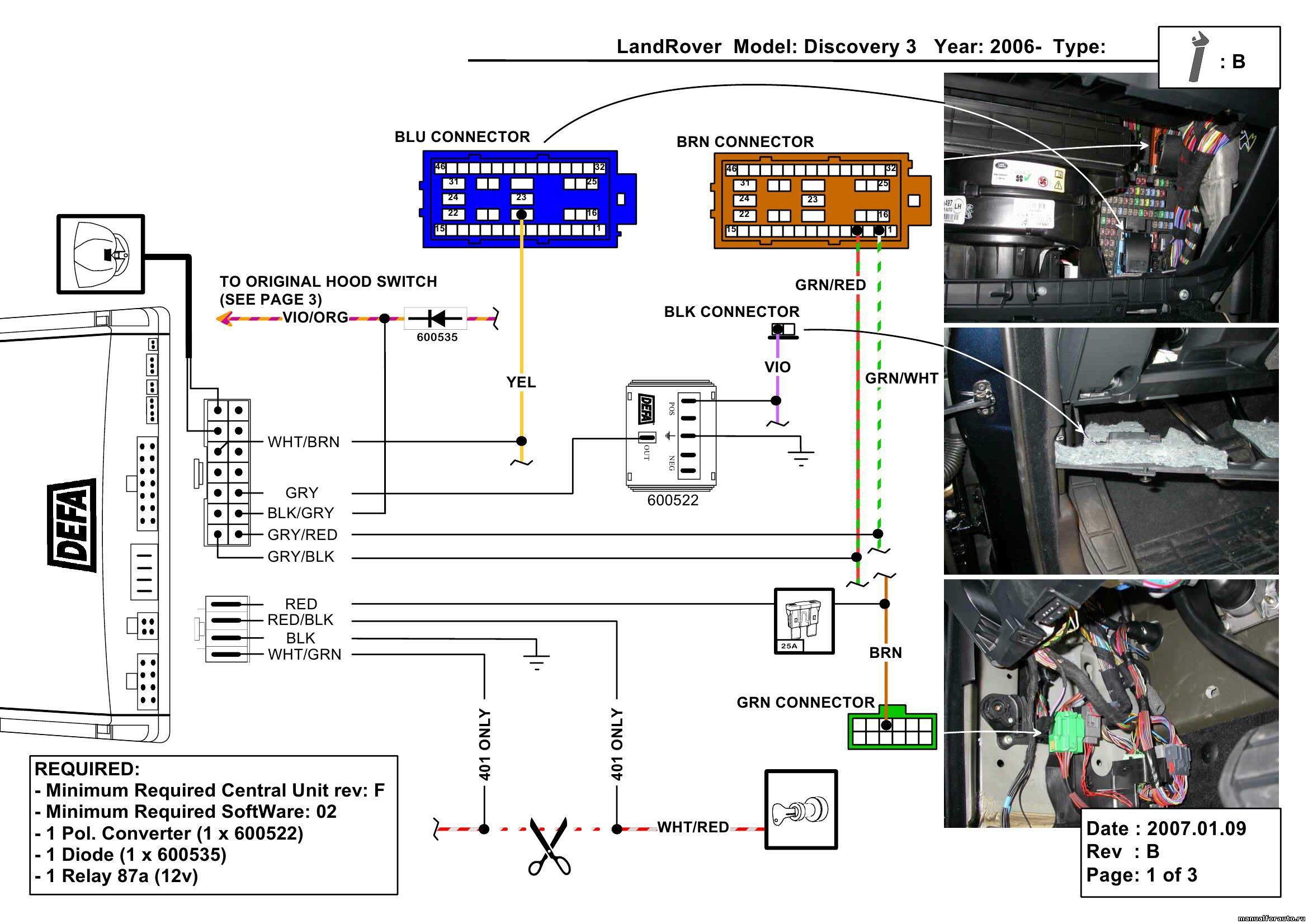

SPECIFIC VEHICLE ALARM FITTING INSTRUCTIONS Land Rover Discovery 3
GENERAL CONNECTIONS FOR INSTALLATION
ALARM/SIREN POSITION
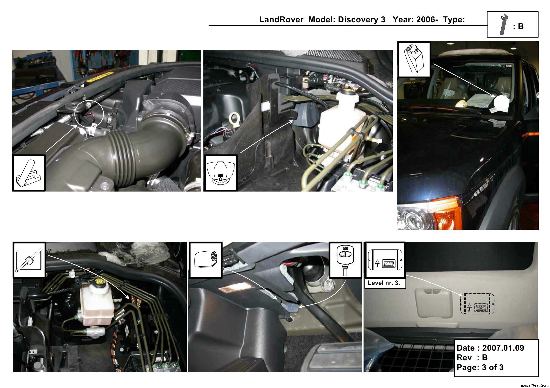
Position compact alarms and sirens on the left of the brake-servo in the engine compartment. Position modular control units and modules under the driver side dashboard behind the plastic protection
POWER SUPPLY
+30: Connect to the В R OWN 2,5 mm2 wire at the exit from the ignition lock.
Alternatively: Connect to the В ROWN wire in the green 12-way connector behind the side wall on the driver side.
-31: Connect to a M6-bolt under the driver side dashboard on the left of the steering column. Alternatively:
Connect to one of the two ground bolts available behind the side wall on the driver side.
IGNITION WIRE
+15/54: Connect to the YELLOW 2,5 mm. wire at the exit from the ignition lock.
Alternatively:
Connect to the YELLOW wire in pos. n. 19 of the blue 46-way connector in the fuse-box on the passenger side behind the glove-compartment.
DIRECTION INDICATORS
Locate the brown 46-way connector in the fuse-box on the passenger side, behind the glove-compartment. Connect to the G REEN- RED wire in pos. n. 4 and to the G REEN-WHITE wire in pos. n. 2
ELECTRIC WINDOWS
No information available.
ENGINE CUT
No information available.
CRANK INHIBITION
+50: Cut the WHITE- RED 2,5 mm2 wire at the exit from the ignition lock.
Remark: During the cranking phase, measure the value of the electrical current in the circuit that has been cut, to make sure that it does not exceed the technical specifications of the product. Install an additional relay if necessary.
BONNET SWITCH
Connect to the ОRANGE-VIOLET wire in the black connector under the engine bonnet hook.
DOORS AND BOOT SWITCH
Positive polarity control
Connect to the VIOLET 1 mm. wire in the black 2-way connector in the courtesy light that is located under the driver side dashboard, on the wall above the pedals.
CENTRAL DOOR LOCKING
Negative control
Locate the green connector behind the console in the mid of the dashboard.
Connect to the PINK- RED wire (lock) and to the PINK-YELLOW wire (unlock)
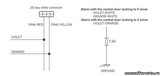
install the protection fuse as close as possible to the point of connection to the vehicle's electrical system.
GSM ANTENNA POSITION
Position the GSM antenna behind the plastic protection of the driver side pillar, with the adhesive side facing towards the windscreen.
GPS ANTENNA POSITION
Position the GPS antenna under the driver side dashboard, over the air vent on the left side
HORN CONTROL
Positive control
Connect to the VIOLET-YELLOWwire on the horn, behind the front grille.

install the protection fuse as close as possible to the point of connection to the vehicle's electrical system.
Position compact alarms and sirens on the left of the brake-servo in the engine compartment. Position modular control units and modules under the driver side dashboard behind the plastic protection
POWER SUPPLY
+30: Connect to the В R OWN 2,5 mm2 wire at the exit from the ignition lock.
Alternatively: Connect to the В ROWN wire in the green 12-way connector behind the side wall on the driver side.
-31: Connect to a M6-bolt under the driver side dashboard on the left of the steering column. Alternatively:
Connect to one of the two ground bolts available behind the side wall on the driver side.
IGNITION WIRE
+15/54: Connect to the YELLOW 2,5 mm. wire at the exit from the ignition lock.
Alternatively:
Connect to the YELLOW wire in pos. n. 19 of the blue 46-way connector in the fuse-box on the passenger side behind the glove-compartment.
DIRECTION INDICATORS
Locate the brown 46-way connector in the fuse-box on the passenger side, behind the glove-compartment. Connect to the G REEN- RED wire in pos. n. 4 and to the G REEN-WHITE wire in pos. n. 2
ELECTRIC WINDOWS
No information available.
ENGINE CUT
No information available.
CRANK INHIBITION
+50: Cut the WHITE- RED 2,5 mm2 wire at the exit from the ignition lock.
Remark: During the cranking phase, measure the value of the electrical current in the circuit that has been cut, to make sure that it does not exceed the technical specifications of the product. Install an additional relay if necessary.
BONNET SWITCH
Connect to the ОRANGE-VIOLET wire in the black connector under the engine bonnet hook.
DOORS AND BOOT SWITCH
Positive polarity control
Connect to the VIOLET 1 mm. wire in the black 2-way connector in the courtesy light that is located under the driver side dashboard, on the wall above the pedals.
CENTRAL DOOR LOCKING
Negative control
Locate the green connector behind the console in the mid of the dashboard.
Connect to the PINK- RED wire (lock) and to the PINK-YELLOW wire (unlock)
GSM ANTENNA POSITION
Position the GSM antenna behind the plastic protection of the driver side pillar, with the adhesive side facing towards the windscreen.
GPS ANTENNA POSITION
Position the GPS antenna under the driver side dashboard, over the air vent on the left side
HORN CONTROL
Positive control
Connect to the VIOLET-YELLOWwire on the horn, behind the front grille.
install the protection fuse as close as possible to the point of connection to the vehicle's electrical system.
